Technical Forum
2019-08-29
Discussion on BLDC - Control of Brushless DC Motors
※Introduction to the Brushless Motor
A motion system using a brush motor can be a good, simple and efficient solution to meet the variable speed drive requirement.
Although the brush motor has good control and durability, its performance and application range are limited due to sparks and commutation problems.
With the advancement of modern technology and the development of micro-controller operation processing and control techniques, there's no need to use a mechanical commutation structure to complete commutation; on the contrary, electronic commutation is used to meet this demand.
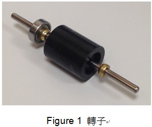
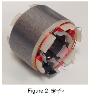
Like the brush motor, the brushless motor also has coils and permanent magnets. But the difference is that for the brushless motor (Figure 3), the coil is now attached to the stator (Figure 2), while the rotor (Figure 1) is made of permanent magnets.

For brushless motors, this new mechanical structure provides several advantages over brush motors, including:
1.Better speed-torque characteristics: Brushless motors no longer lose output torque due to contact friction with brush structures.
2.High dynamic response: As the rotor of the brushless motor is composed of permanent magnets, it has a lower point of inertia.
3.Efficiency and reliability: brushless motors no longer have the problem of voltage drop (loss) due to contact issues in commutation structures.
4.Long operating life: There is no need to consider follow-up maintenance of the commutation structure for the brushless motor.
5.Lower electronic noise: As no arc is generated during commutation, there is no issue with electromagnetic interference caused by the electronic signal noise.
6.Higher speed range: The brushless motor has no limitation due to brush commutation contact parts.
7.Improvable motor characteristics: As electronic commutation is used for brushless motors, circuit technology can be used to improve commutation performance.
With these advantages, brushless motors play an important role in many fields, including:
§ Automobile:
(1) Electric and hybrid vehicles
(2) Electric motorcycles and electric scooters
(3) Electric skates
§ Household appliances:
(1) Blenders
(2) Hand-held power tools
(3) Electric fans
(4) Robot sweepers
(5) Kitchen ventilation
(6) Washing machines
(7) Indoor air conditioning and refrigerators
§ Industrial applications:
(1) Linear motors
(2) Servo motors
(3) Injection molding equipment
(4) Industrial robots
(5) Automatic handling equipment
※ Operation Principle of Brushless Motors
A basic motor is a device that converts electrical energy into mechanical energy.
This kind of energy conversion begins with the introduction of a current into one or more wires to generate a magnetic field. Then, due to the polarity of the magnetic field, the magnetic field produced by the wire moves with the force of the permanent magnet.
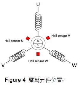
To generate a specific magnetic field sequence to drive the rotor on a brushless motor, it is necessary to confirm the position of the permanent magnet on the rotor. The two main methods used to determine the rotor position are:
●Hall sensor: It is installed on the stator to detect the position of the rotor and provide the trigger timing of the power components (Figure 4).
●Back-EMF signal detection: This detection method is the main sensorless technology. The position of the rotor is estimated by measuring the terminal voltage (back electromotive force) of the unactivated magnetic phase. Because the back-EMF signal is used as rotor position information, there needs to be special control processing between static and start-up status (before the back-EMF signal has not been established or recognized).
By using the two methods above to obtain rotor position information to switch the path through which the current flows, the brushless motor can complete the commutation and commence periodic rotation performance.
The commonly used commutation techniques for brushless motors include six-step square wave, sine wave, and magnetic field-oriented control (FOC) (or vector control).
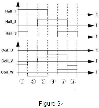
1. Six-step square wave
When using the six-step square wave driving mode, it is often detecting the position of the rotor by directly using Hall sensor components. This is a simple method, and the most popular. Take a commonly used three-phase motor as an example: from an electrical angle conversion perspective, the phase current conducts 120 degrees at an electrical angle, then turns off 60 degrees, then conducts 120 degrees in the opposite direction and turns off 60 degrees (Figure 6 ). The main control principle is to allow the current to flow through only two of the three sets of windings so that the brushless motor can rotate.
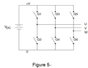
The circuit structure of the power end used to drive the three-phase motor is a three-phase bridge converter circuit.
Figure 5 is a basic concept of a three-phase bridge converter circuit.
When the Hall sensor is used to detect the rotor position in the six-step square wave driving mode, the opening and closing time of the bridge converter is shown in the Figure 6.
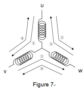
Direction of the three-phase current flow as indicated in Figure 7
1. Sine wave
If we were to take sine waves instead of square waves to drive brushless motors, in each phase coil, a voltage in the form of a sine wave is applied following a specific timing sequence to control the inflow and outflow of the motor current. When driving the motor in this way, the resolution of the rotor position sensed alone by the Hall component is insufficient. Usually a high-resolution sensor is needed to respond to the rotor position.
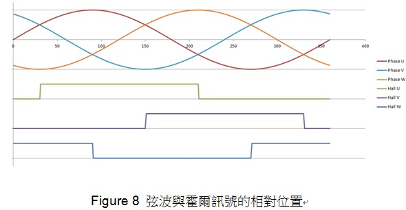
Figure 8 Relative position of a sine wave and Hall signal
2. Field-oriented control (FOC)
This control method requires a more complicated circuit design and a microcontroller of high operational capability. This method is based on a calculation of the current and voltage vectors to determine the commutation timing of the motor. It is mainly to control the current, so it can be used in some applications for which speed is frequently switched, but that require a specific torque output.
※Speed-Torque diagram
Figure 9 is a common speed-torque diagram of brushless motors.
The two torque parameters of brushless motors include the blocked-rotor torque and rated torque.
The two torque parameters of brushless motors include the blocked-rotor torque and rated torque.
The blocked-rotor torque is a point on the diagram, namely the maximum point of the torque output when the motor output shaft does not rotate.
The rated torque is another point on the diagram that operates at a more efficient point when the motor is running. It is very important to select the correct form of motor in a given application. The parameters include the maximum output torque and the expected speed range.
If there are frequent starts and stops in the application, or even frequent reversals under additional external loads, the motor will be operated between the rated output torque and the blocked-rotor torque. When the motor starts to rotate from a static state to an accelerated state, there must be a large output torque to overcome the external load and the inertia of the motor itself. At this stage, even the maximum torque, namely blocked-rotor torque, will be used.
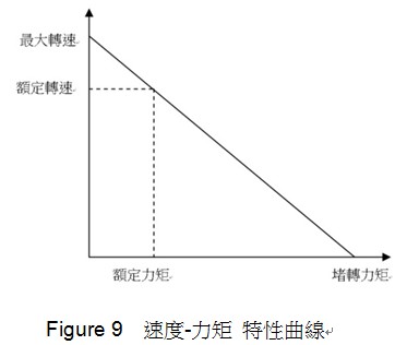
If there is no frequent speed change when in use, the motor can be operated at the rated speed. When the motor is applied to a specific operating speed range, it is safe to select a rated speed of the motor above the average running speed.
※ Application of Brushless Motors
●Application of a Fixed Load
In some applications, allowing a slight change in speed is more important than maintaining accurate speed. In these applications, the load is usually directly connected with the motor output shaft, such as a fan. A low-cost controller is usually required for this application, mainly using the so-called "open loop".
●Application of a Variable Load
This requires a wide range of motor speed changes. These application examples may require high-speed control accuracy and a good dynamic response. Common applications include household electric equipment, washing (drying) machines, air-conditioning compressors, pumps and robots.
●Positioning applications
In this field of application, the system usually needs to adopt close-loop control. The main control functions include torque control, speed control and position control. To achieve close-loop control, so-called "sensors" (such as an encoder) are required to provide the actual speed and position of the motor.